By Cole Rutkowski

For my final project in MCEN 1025, I was tasked with modeling and assembling an object
in my house with a minimum of 3 components. This was the start of my focus on cam design
as a part of my portfolio.
Without a way to disassemble and reassemble, I had to measure every component with hand
tools. This limited the accuracy of some of the measurements, however I was able to
adjust the measurements to fit the model.
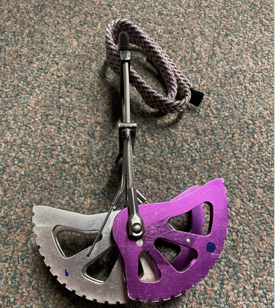
For this project, I learned how to use surfaces, splines, and equation driven curves. At the time, I did not have the equation for the cam lobe, so I inserted a top-down picture of the lobe and drew splines over it. I also used splines for the trigger.
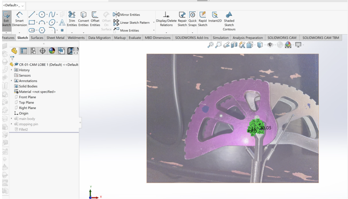
The biggest difficulty I faced was creating drawings that accurately depicted the
dimensions of the product. Because I used splines drawn over an image, I did not
have easily readable dimensions that a machinist would be able to read and measure.

Some key components that I left out in my model were the steel cable loop, polyurethane thumb loop, springs, and trigger wires.
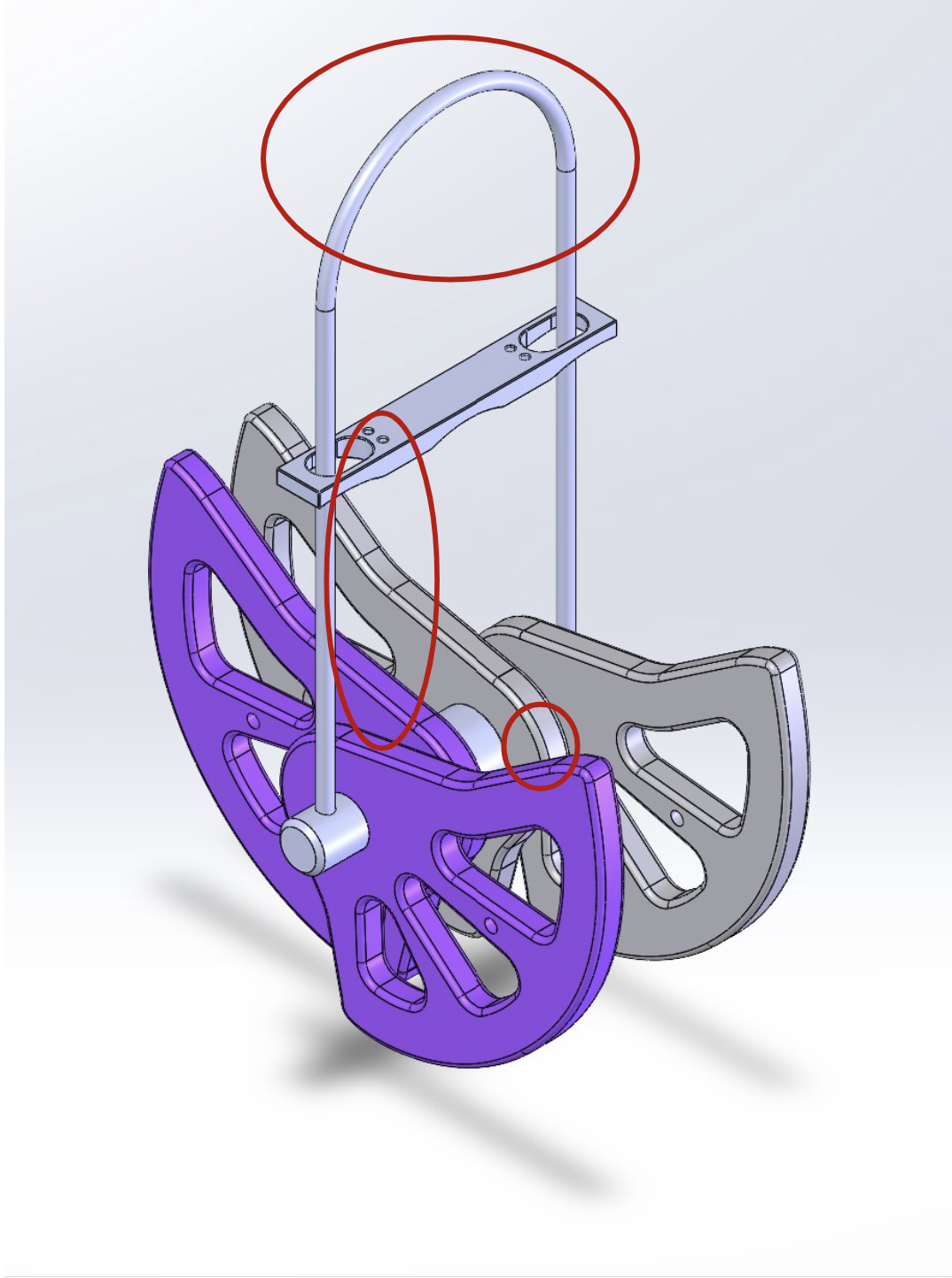
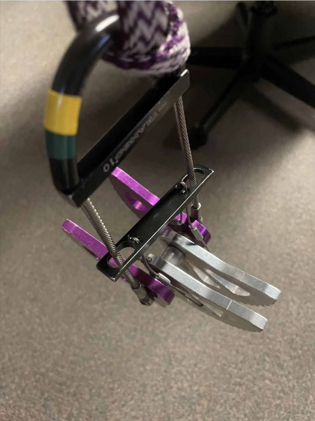
In my assembly, I mated the axle holes to be concentric about the through-axle and the trigger wire holes to be linearly dependent
on the position of the trigger, which allowed the lobes to cam inward when pulling down the trigger on the model.
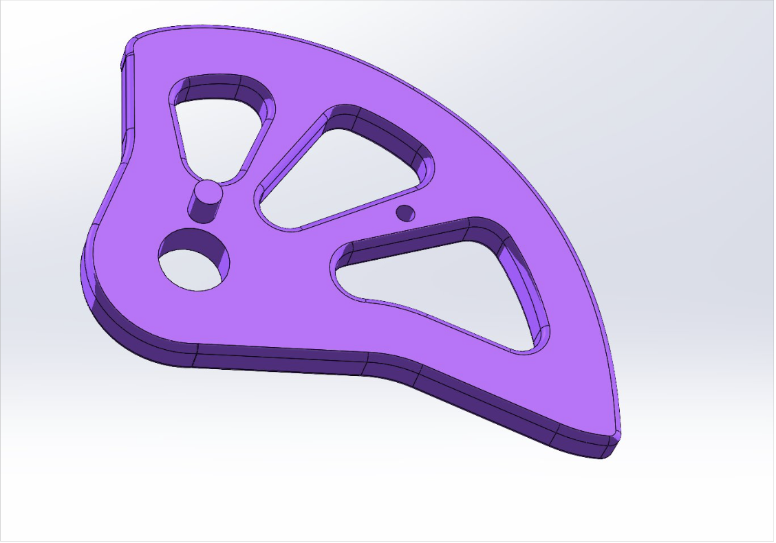
This project was my first attempt at working with complex curves and surfaces. I greatly improved my CAD skills throughout this project and it fueled my desire to improve on them. I also learned how to research new modeling techniques and features that I was not taught in class.